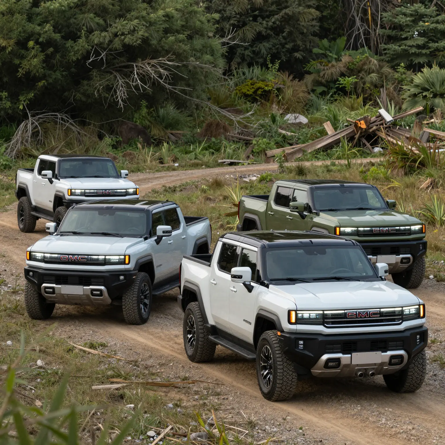

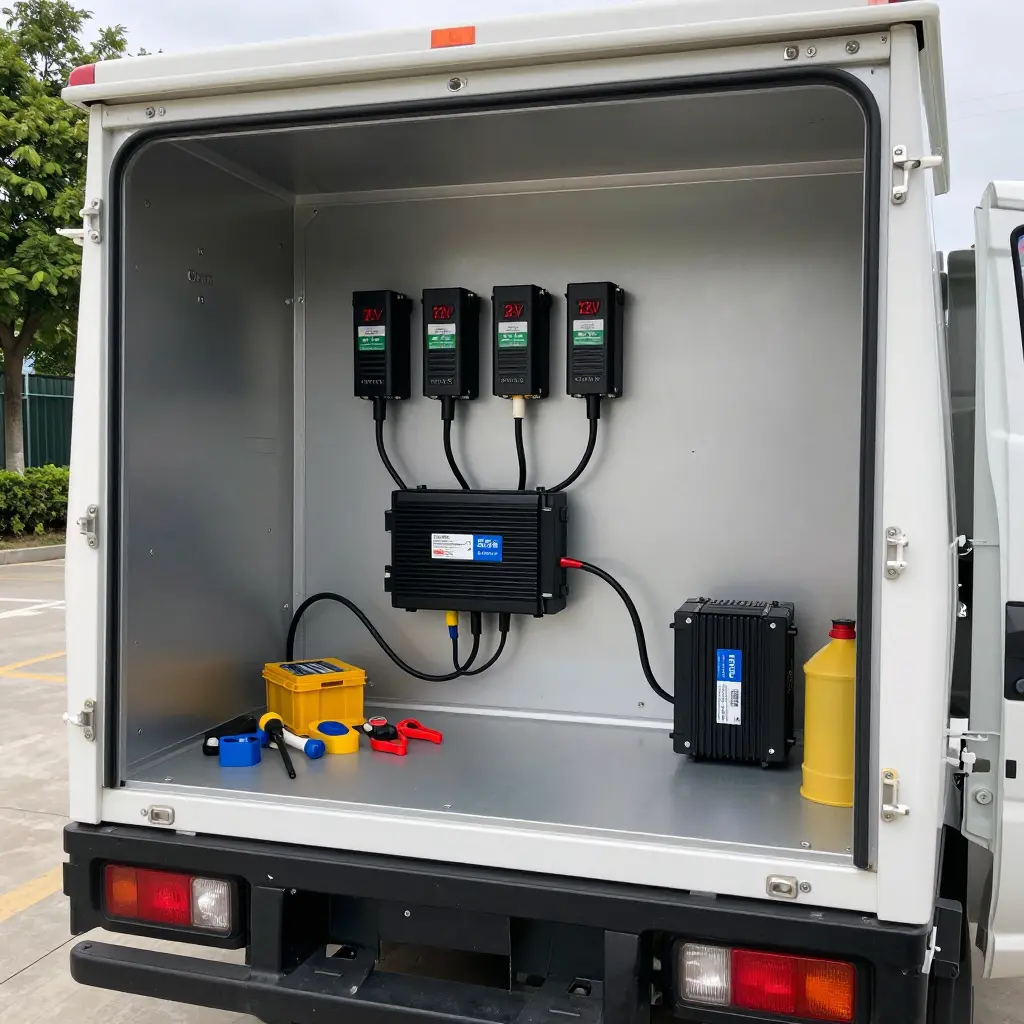
Electric box truck upfitting means converting a battery-electric chassis cab into a working delivery or service vehicle: adding a cargo box, liftgate, refrigeration, interior lighting, and other job-specific equipment. On an electrified platform, all of it eventually draws from the same traction battery that moves the truck.
12V auxiliary loads are the low-voltage systems that run off the vehicle’s 12-volt circuit instead of the high-voltage traction pack: cab lights, fans, radios, telematics units, cameras, and powered tools. Low voltage does not mean low demand. Those loads still pull stored energy, and that energy comes from the traction battery.
A DC-DC converter steps the high-voltage traction battery down to 12V to power those loads. Converter sizing means matching its continuous and peak current output to the total auxiliary demand, so the system runs without overheating or overloading.
For business owners, fleet managers, and upfitters, these choices carry direct consequences. Auxiliary power decisions affect real-world electric truck range and daily operating cost; an undersized converter or an unbudgeted load eats into miles on every route. Teams weighing the broader economics of electrification can review why your business should consider electric trucks.
Why 12V Auxiliary Loads Eat Range
In a diesel box truck, 12V power feels free. The engine turns an alternator, and the alternator converts a sliver of diesel into the electricity that runs headlights, telematics, liftgate controls, cab lights, and radios. The tank gets refilled at every stop, so nobody watches the alternator’s appetite. Its energy never visibly competes with the wheels.
An electric box truck has no engine, no accessory belt, no spinning alternator. The only energy on board sits in the high-voltage traction pack, and every 12V device must be served through a DC-DC converter that steps several hundred volts down to roughly 12 to 14 volts.
One pack, two jobs
The converter is a one-way door into the battery that propels the truck. Every watt delivered to a 12V load is a watt the motors cannot use; the pack pays either way. Range loss therefore scales with average power draw multiplied by duty cycle, not with how urgent the load feels.
Take a 1 kW continuous auxiliary load over an eight-hour shift: 8 kWh of 12V energy. Add conversion losses and the pack gives up roughly 8.7 to 8.9 kWh. On a truck that travels about 2 miles per kWh, that is close to 18 miles of range gone before the truck moves an extra mile.
Conversion losses and the heat they create
A quality DC-DC converter runs at roughly 90% to 94% efficiency, so 6% to 10% of the power it handles becomes heat. Push 1,500 W through one and it may shed 90 to 150 W inside an enclosure that was never meant to be a heater. That heat can trigger extra cooling, and cooling fans or compressors then draw more 12V power, a feedback loop that compounds the original loss.
Think of a garden hose trickling into a pool. The flow looks trivial until it runs all day and the water level tells the truth. Auxiliary loads behave the same way on a traction pack.
Why duty cycle beats peak power
A 2 kW liftgate that runs 30 seconds per stop is cheap. A 300 W telematics unit, camera system, or heater that never switches off is expensive. Peak numbers sell components; average watts decide range. That is why well-matched electric auxiliary power units and accurately sized converters belong in every upfit plan.
| 12V average load | Pack energy used per 8-hour shift | Range lost at 2 mi/kWh |
|---|---|---|
| 300 W | ~2.6 kWh | ~5 miles |
| 700 W | ~6.1 kWh | ~12 miles |
| 1,200 W | ~10.4 kWh | ~21 miles |
| 2,000 W | ~17.4 kWh | ~35 miles |
Assumes a 92% efficient DC-DC converter and a continuous duty cycle. Figures are planning estimates, not test results.
Peak power is loud; average power is what empties the battery. The 12V loads you add during upfitting never stop being traction loads, so converter sizing deserves as much attention as the box itself.
Common 12V Auxiliary Loads in Electric Box Truck Upfitting
On an electric box truck, the 12V side of the build does more work than most fleets expect. Every accessory below draws from the same DC-DC converter, and the total climbs faster than a spec sheet suggests. If you are still choosing a base platform to convert, browse these electric work trucks for sale before you lock in your load list.
- Cargo box interior lighting – Roughly 100-400W, usually on the whole time the rear doors are open. LED strips beat older incandescent fixtures here.
- Liftgate / tail lift – The biggest single draw at about 1,500-3,000W, but only in short bursts. Intermittent, and heavily dependent on duty cycle.
- Refrigeration or reefer unit controls – Controllers, fans, and sensors pull around 200-600W, often continuously on temperature-controlled routes.
- Telematics and GPS – Always-on trackers use just 5-30W each, but they never switch off, so they sit in your continuous baseline whether you count them or not.
- Backup cameras and safety systems – Camera clusters, radar, and sensors draw 10-50W, mostly intermittent, with brief spikes during reversing and low-speed maneuvers.
- Cab HVAC blower – Fan motors consume 200-500W and run effectively continuously across a full shift in hot or cold climates.
- Work lights – Exterior flood and scene lighting runs 100-500W, mostly while parked at job sites.
- Hydraulic pump controllers – Solenoids and electronics pull 50-200W, and only while the pump actually engages.
- Communication or dispatch equipment – Radios and mobile data terminals use 20-100W and run continuously whenever the truck is in service.
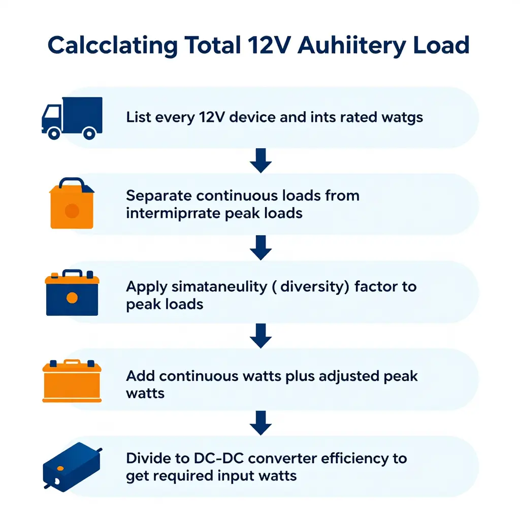
Add these up honestly before you size the converter. Continuous loads set your steady-state draw, while intermittent spikes like the liftgate decide how much surge headroom you need.
Estimated Driving Range Loss vs. Continuous 12V Auxiliary Load
Every watt pulled from the 12V system on an electric box truck comes out of the pack that moves the vehicle. The more equipment you run continuously – lifts, refrigeration, tool chargers, lights, telematics – the more range disappears. The chart below shows the relationship across six common load levels.
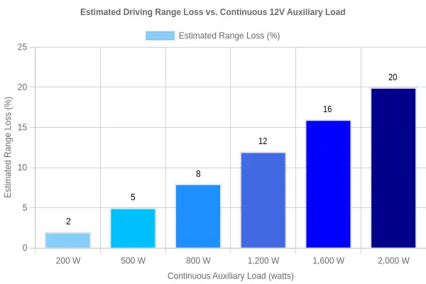
Chart specifications
- Chart title: Estimated Driving Range Loss vs. Continuous 12V Auxiliary Load
- X-axis label: Continuous Auxiliary Load (watts) – bars at 200 W, 500 W, 800 W, 1,200 W, 1,600 W, and 2,000 W
- Y-axis label: Estimated Range Loss (%) – scaled 0 to 25
- Suggested bar colors: A single-hue electric-blue gradient that darkens as load rises – light sky blue (#87CEFA) at 200 W stepping through #00BFFF, #1E90FF, #4169E1, and #0000FF to deep navy (#00008B) at 2,000 W
The numbers behind the bars
| Continuous Auxiliary Load | Estimated Range Loss |
|---|---|
| 200 W | 2% |
| 500 W | 5% |
| 800 W | 8% |
| 1,200 W | 12% |
| 1,600 W | 16% |
| 2,000 W | 20% |
The takeaway
Range loss climbs roughly linearly with continuous auxiliary load, so every additional constant watt draws down usable driving distance at a predictable pace. That is why the converter and load budget deserve as much planning as the payload.
Note: The values above are illustrative estimates for planning only. Real-world range loss depends on pack size, drive cycle, temperature, converter efficiency, and duty cycle, so recalculate these figures using your actual vehicle data before finalizing an upfit.
When you are ready to translate those watts into hardware, it helps to understand how sizing auxiliary power units affects the rest of the electrical system.
How Auxiliary Power Flows in an Electric Box Truck
Before you can size a converter, it helps to see where the power comes from. The diagram below traces energy from the high-voltage traction pack through the DC-DC converter and into the 12V auxiliary distribution block that feeds your upfit loads.
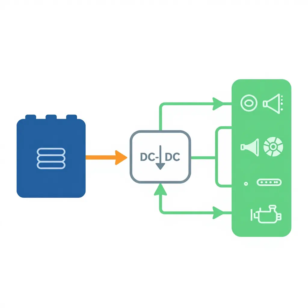
Left to right: the deep-blue block is your traction battery, and the thick orange double arrow is the high-voltage feed to the converter in the center. The converter steps that voltage down, and the thinner green line carries protected 12V current into the distribution block, where it splits across your headlights, horn, fan, lighting strips, pump, and other accessories. Everything you add to the box body is ultimately paid for by the same traction pack that moves the truck, so every extra amp of 12V draw trims usable range.
DC-DC Converter Selection Criteria and Common Mistakes
Picking the right DC-DC converter is the difference between an upfit that runs all day and one that shuts down on the first cold morning. The converter steps your high-voltage traction pack down to the 12V or 24V that your liftgate, reefer, lighting, and telematics expect. Get the specs right and the truck behaves like a factory build.
Converter selection starts with the current rating. Size for continuous load rather than idle draw, then check the peak rating against the biggest surge on the truck. Match the input voltage window to your pack’s real operating range, not its nominal label. A 400V-class pack might swing from 330V to 460V, and a converter that drops out at the low end will strand your loads.
Output regulation matters too. Decide whether you need a fixed 12V or 24V output or a float profile that tracks a battery. If you keep an existing lead-acid bank for backup, a float setting keeps it topped up. Efficiency is another lever: a 92% efficient unit wastes far less pack energy than an 85% one, and that shows up as range.
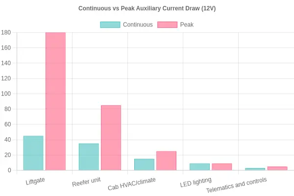
Thermal management and cooling method come next. Convection-cooled converters suit mild climates, while forced-air or liquid-cooled units handle sealed compartments and high ambient heat. Check the IP rating and environmental protection for dust, water, and road spray, confirm whether isolation is required for safety and noise, and verify the CAN or control interface so the unit can report faults to your vehicle network. Fleets standardizing their builds often anchor the auxiliary architecture on proven electric mid-size truck platforms.
Now the mistakes. Undersizing for peak liftgate or reefer surges is the most common. Ignoring simultaneous loads, such as a liftgate running while the reefer cycles, stacks current past the rating. Overlooking conversion efficiency losses means the pack pays for every watt the converter burns. Neglecting cable and fuse sizing creates voltage drop and heat that no spec sheet can fix.
Common mistakes to avoid
- Sizing on continuous current alone and ignoring inrush peaks
- Treating each load as if it runs by itself
- Forgetting efficiency losses in range calculations
- Running undersized cable or fuses for the actual circuit length
Get each criterion right, and the converter stops being a weak link. It becomes one more reliable part of the truck.
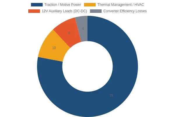
Where Does the Traction Battery Energy Actually Go?
On a representative electric box truck, the motive power that turns the wheels is only part of the story. Rolling, heating, cooling, and lighting all pull from the same battery pack. The doughnut chart above breaks down that budget.
| Consumption Category | Illustrative Share | Notes |
|---|---|---|
| Traction / motive power | 78% | Propelling the loaded box truck |
| Thermal management / HVAC | 10% | Battery conditioning, cabin heat, and cooling |
| 12V auxiliary loads (DC-DC) | 8% | Lights, telematics, liftgate, lighting bodies, accessories |
| Converter efficiency losses | 4% | Heat lost stepping HV down to 12V |
Color scheme: a deep electric blue for traction, amber for HVAC, coral for 12V auxiliary loads, and neutral gray for conversion losses, so the non-traction slices stand out against the dominant motive-power share.
How Auxiliary and Conversion Losses Shrink Your Range
Add the 12V auxiliary loads to the converter losses and roughly 12% of the pack’s energy goes to systems that never move the truck. Include HVAC and about a fifth of your battery budget goes to housekeeping instead of mileage, trimming usable range on every duty cycle. If you are spec’ing these downstream systems, it is worth understanding how dedicated auxiliary power units interact with the main pack.
Note: This split is illustrative only. Actual shares vary significantly by duty cycle and climate – a refrigerated route in Phoenix in July will push HVAC and auxiliary loads far higher, while a mild-climate, low-idle route will let traction power claim a much larger slice.
FAQ: Converter Sizing and Auxiliary Loads
How much range do 12V auxiliary loads actually cost?
Every watt drawn by auxiliary loads is pulled from the traction battery through the DC-DC converter, so it comes straight off your driving range. A continuous 1 kW load on a truck that consumes about 1.5 kWh per mile costs roughly 0.67 miles for every hour it runs. A liftgate cycled 40 times a day may only add 2 to 4 miles of consumption, but steady loads like work lights, cab climate, or a powered ramp accumulate hundreds of watt-hours per shift. The rule of thumb: divide the load in watts by 1,000, then by your truck’s kWh-per-mile figure to get miles lost per hour.
Do I size the converter for continuous or peak load?
Size for continuous load first, then verify the peak. The converter must carry your steady-state auxiliary loads without overheating, because it runs at that level for the entire shift. Peak demand, such as a liftgate motor’s inrush or a compressor start, lasts only seconds and is usually handled by the converter’s short-term overload rating or by a separate battery buffer. If the peak exceeds the converter’s surge capacity, the equipment will brown out or the unit will shut down.
What size DC-DC converter does a box truck with a liftgate need?
Most medium-duty electric box trucks with a hydraulic liftgate need a 2.5 kW to 4 kW DC-DC converter. A typical liftgate draws 1.5 kW to 2.5 kW while running, plus 300 W to 800 W for cab and body electronics. Check whether the liftgate has its own dedicated battery, since that changes the continuous draw on the converter. Vocational body loads behave differently across truck types, as this overview of vocational electric truck bodies shows.
Can I run a reefer unit from the 12V system?
Only for small transport refrigeration units, and only with a properly sized converter. A full-size reefer can draw 3 kW to 8 kW continuously, which quickly overwhelms a standard 12V DC-DC converter and drains the traction battery. Small units on insulated vans are sometimes run this way, but dedicated high-voltage reefer systems or an auxiliary power unit are the practical choice for anything larger. Always confirm the unit’s continuous amp draw before committing.
How much headroom should I add?
Add 20% to 30% headroom above your calculated continuous load. Auxiliary loads rarely match their nameplate rating, and add-ons accumulate over a truck’s life, so a converter sized exactly to today’s demand will run hot and age fast. Headroom also keeps the converter in its most efficient operating band and absorbs future upfitting. Undersizing is a common and expensive mistake in electric box truck conversions.
Does converter efficiency really matter for range?
Yes, but only at the margins. A converter running at 93% versus 97% efficiency wastes roughly 40 W on a 1 kW load, which is about 0.03 miles per hour of operation, negligible on its own. Efficiency matters more when loads are large and constant, because the loss scales with power. Buy a converter with a flat efficiency curve across your actual load range rather than chasing a single peak-efficiency number.
| Application | Continuous Load | Recommended Converter |
|---|---|---|
| Cab electronics and lights | 0.3 – 0.8 kW | 1.5 kW |
| Liftgate (dedicated battery) | 0.5 – 1.5 kW | 2.5 kW |
| Liftgate (direct feed) | 1.5 – 2.5 kW | 3.5 – 4 kW |
| Small reefer unit | 3 – 8 kW | 5 kW + dedicated HV system |
The Bottom Line on Upfitting for Range Efficiency
Every 12V auxiliary load in an electric box truck ultimately draws its power from the traction battery, routed through the DC-DC converter. That single truth explains why upfitting choices shape range so directly. Lights, liftgates, refrigeration, telematics, and cab electronics all add to the continuous and peak demand the converter must serve, and every watt it delivers is a watt the truck can no longer spend moving cargo. Get the converter sizing wrong, and you tax the very range you are trying to protect.
The practical takeaway comes down to four steps. First, inventory every auxiliary load so nothing is left off the list. Second, apply realistic duty-cycle factors, since few devices run at full nameplate draw all day. Third, add sensible headroom to absorb peaks and future add-ons. Finally, match converter ratings to the measured continuous and peak demand rather than to guesswork. Done in that order, sizing stops being a shot in the dark.
This is where working with a partner who understands electric special trucks matters. As a B2B supplier, EV Special Trucks offers custom configurations and full-set export solutions built for international dealers and fleet partners. Whether you are weighing the business case for electrification or sourcing through a dedicated electric semi truck dealer, the same principle holds: the right converter, sized to real demand, keeps your fleet running at the range it was meant to deliver. That is the advantage behind every well-planned electric truck investment.